Current Electricity
Chapter–3
CURRENT ELECTRICITY
ELECTRIC CURRENT
It is the rate of flow of charge through any cross section.
i.e.
Conventionally, the direction of flow of positive charge is taken as the direction of electric current. It is a scalar quantity and its S.I. unit is ampere (A).
POINTS TO REMEMBER
Current carriers in conductors are electrons, (valence e–s) ions in electrolytes, electrons & holes in semiconductors and positive ions /electrons in gases.
Charge of electron = 1.6 × 10⁻¹⁹c
1 ampere = 6.25 × 10¹⁸ electrons/sec
Though direction is associated with current (opposite to the motion of electrons), it is not a vector quantity as it does not follow rules of vector addition.
For a current to flow through a cross-section, there must be a net flow of charge through that cross-section.
In a metal like copper there are around 1028 free electrons per m3 moving randomly in all directions with speeds of the order of 106 m/s even in the absence of an electric field. But since the number of electrons passing through a cross-section from left to right is equal to the number of electrons passing from right to left in a given time, therefore the net charge flow is zero and hence the electric current is zero.A conductor remains unchanged when current flows in it. i.e. Net charge in a current carrying conductor is zero.
CURRENT DENSITY
Current density at a point inside a conductor is defined as the amount of current flowing per unit cross sectional area around that point of the conductor, provided the area is held in a direction normal to the direction of current.
i.e. Current density,
If area is not normal to current, then area normal to current is A' = A cos θ (see the figure)

or I = J A cos θ or
Its SI unit is Am–2
Current density can also be related to electric field as
where σ is conductivity of the substance & ρ is specific resistance of the substance.
J is a vector quantity and its direction is same as that of .
Dimensions of J are [M°L–2T°A]
POINTS TO REMEMBER
Electric current is a macroscopic physical quantity whereas current density is a microscopic physical quantity.
For a given conductor current does not change with change in cross-sectional area.
DRIFT VELOCITY
When the ends of a conductor are connected to the two terminals of a battery, an electric field is set up in the conductor from the positive terminal to the negative terminal. The free electrons in the conductor experiences a force opposite to the direction of the electric field and hence get accelerated. However this process of acceleration is soon interrupted by collision with ions of solid. The average time for which each electron is accelerated before suffering a collision is called the mean free time or mean relaxation time.
Thus, the free electrons within the metal, in addition to its random motion acquire a small velocity towards the positive end of the conductor. This velocity is called drift velocity. It is given by
,
where e is the charge and m is the mass of electrons.
is the electric field established in a conductor and is the average relaxation time.
Negative sign is because the directions of and (for electron) are opposite.
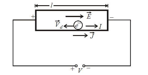
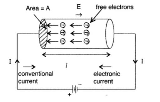
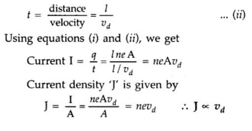
where V is the potential difference across ends of the conductor of length l. The uniform current I, flowing through the conductor is given by
I = n e A vd
where n = number of free electrons per unit volume,
A = area of cross-section, vd = drift velocity
In vector form,
The negative sign is because the direction of drift velocity of electron is opposite to .
Mobility - Drift velocity per unit electric field is called mobility. It is denoted by µ.
Its S.I. unit is m2/volt-sec.
POINTS TO REMEMBER
Drift velocity is very small, it is of the order of 10–4m/s which is negligible as compared to thermal speed of e–s at room temperature (105 m/s)
The drift velocity is given by
where, J = current density
e = electronic charge = 1.6 × 10⁻¹⁹ C
n = the number of free electrons per unit volume
The number of free electrons per unit volume (n) can be determined by the following relation :
and
where N0 = Avogadro number
d = density of the metal
M = molecular weight
and x = number of free electrons per atom
For steady current :
; ;
This means that for a given material and steady current in case of non-uniform cross-section of material
; ;
Variation of drift velocity :
; Vd ∝ E
when length is doubled, vd becomes half and
when V is doubled, vd becomes twice.
OHM’S LAW AND ELECTRICAL RESISTANCE
When a potential difference is applied across the ends of a conductor, a current I is set up in the conductor.
According to Ohm’s law “Keeping the given physical conditions such as temperature, mechanical strain etc. constant, the current (I) produced in the conductor is directly proportional to the potential difference (V) applied across the conductor”.
i.e., or ... (1)
where K is a constant of proportionality called the conductance of the given conductor.
Alternatively, or V = RI ... (2)
where the constant R is called the electrical resistance or simply resistance of the given conductor.
From above two eqs. it is clear that R = 1/K.
If a substance follows Ohm’s law, then a linear relationship exists between V & I as shown by figure 1. These substances are called Ohmic substances. Some substances do not follow Ohm’s law, these are called non-ohmic substance (shown by figure 2)
Diode valve, triode valve and electrolytes, thermistors are some examples of non-ohmic conductors.

Slope of V-I Curve of a conductor provides the resistance of the conductor
slope = tan θ =
The SI unit of resistance R is volt/ampere = ohm (Ω)
ELECTRICAL RESISTANCE
On application of potential difference across the ends of a conductor, the free e–s of the conductor starts drifting towards the positive end of the conductor. While drifting they make collisions with the ions/atoms of the conductor & hence their motion is obstructed. The net hindrance offered by a conductor to the flow of free e–s or simply current is called electrical resistance. It depends upon the size, geometry, temperature and nature of the conductor.
Electric Resistivity
Electric resistivity is defined as the electrical resistance offered per unit length and unit cross-sectional area at a specific temperature. It is denoted by ρ. It is also known as specific electrical resistance. Its formula is:
Electrical resistivity is the reciprocal of electrical conductivity and is a measure of the ability of a material to oppose the flow of current. Metals are good resistors of electricity and thus have low resistivity. Insulators such as rubber, glass, and graphite have high resistivity. Semiconductors' resistivity decreases with an increase in temperature and is also affected by the presence of impurities.
RESISTIVITY
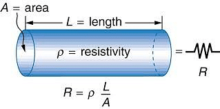
For a given conductor of uniform cross-section A and length l, the electrical resistance R is directly proportional to length l and inversely proportional to cross-sectional area A
i.e., or or
ρ is called specific resistance or electrical resistivity.
Also,
The SI unit of resistivity is ohm - m.
Formula of Resistivity: The materials with the electric field and current density have the given resistivity formula i.e. ρ = E/J. Here ρ is the resistivity of the material, E is the magnitude of the electric field and J is the magnitude of current density. Conductors with a uniform cross-section and uniform flow of electric current can use the formula ρ =R A/l.
Resistivity of Different Materials
The resistivity of different materials is listed in the table below:
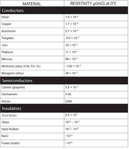
Resistivity of Different Materials
CONDUCTIVITY
It is the reciprocal of resistivity i.e. .
The SI unit of conductivity is Ohm–1m–1 or mho/m.
Ohm’s law may also be expressed as, J = σE
where J = current density and E = electric field strength
Conductivity, where n is free electron density, τ is relaxation time and m is mass of electrons.
The value of ρ is very low for conductors, very high for insulators & alloys, and in between those of conductors & insulators for semiconductors.
Resistance is the property of an object while resistivity is the property of material.
MATERIALS AND THEIR RESISTIVITY

COMMON DEFAULT
Since
It is incorrect to think that if the length of a resistor is doubled its resistance will become twice.
If you look with the eye of a physicist you will find that when l changes, A will also change. This is discussed in the following article.
Case of Reshaping a Resistor
On reshaping, the volume of a material is constant.
i.e., Initial volume = final volume
or, Ai li = Af lf ... (i)
where li, Ai are initial length and area of cross-section of resistor and lf, Af are final length and area of cross-section of resistor.
If initial resistance before reshaping is Ri and final resistance after reshaping is Rf then
... (ii)

From eqs. (i) and (ii)
,

This means that resistance is proportional to the square of the length during reshaping of a resistor wire.
Also from eqs. (i) and (ii)
,

This means that resistance is inversely proportional to the square of the area of cross-section during reshaping of the resistor.
Since A = π r2 (for circular cross-section)

where r is the radius of the cross section.
EFFECT OF TEMPERATURE ON RESISTANCE AND RESISTIVITY
Resistance of a conductor is given by Rt = R0 (1 + α Δt)
Where α = temperature coefficient of resistance and Δt = change in temperature
FOR METALLIC CONDUCTORS
If ρ1 and ρ2 be resistivity of a conductor at temperature t1 and t2, then
ρ2 = ρ1 (1 + α Δ T)
where α = temperature coefficient of resistivity and
where ΔT = t2 – t1 = change in temperature
The value of α is positive for all metallic conductors.
∴ ρ2 > ρ1
In other words, with rise in temperature, the positive ions of the metal vibrate with higher amplitude and these obstruct the path of electrons more frequently. Due to this the mean path decreases and the relaxation time also decreases. This leads to an increase in resistivity.
Please note that the value of α for most of the metals is
FOR ALLOYS
In case of alloys, the rate at which the resistance changes with temperature is less as compared to pure metals.
For example, an alloy manganin has a resistance which is 30-40 times that of copper for the same dimensions.
Also the value of α for manganin is very small ≈ 0.00001°C–1. Due to the above properties manganin is used in preparing wires for standard resistance (heaters), resistance boxes etc.
Please note that eureka and constantan are other alloys for which ρ is high. These are used to detect small temperatures, protect picture tubes / windings of generators, transformers etc.
For semiconductors : The resistivity of semiconductors decreases with rise in temperature. For semiconductors the value of α is negative.

With rise in temperature, the value of n increases. Please note that it decreases with rise in temperature. But the value of increase in n is dominating for the value of ρ in this case.
For electrolytes : The resistivity decreases with rise in temperature. This is because the viscosity of electrolyte decreases with increase in temperature so that ions get more freedom to move.
For insulators : The resistivity increases nearly exponentially with decrease in temperature. Conductivity of insulators is almost zero at 0 K.
Superconductors : There are certain materials for which the resistance becomes zero below a certain temperature. This temperature is called the critical temperature. Below critical temperature the material offers no resistance to the flow of e–s. The material in this case is called a superconductor. The reason for superconductivity is that the electrons in superconductors are not mutually independent but are mutually coherent. This coherent cloud of e–s makes no collision with the ions of super-conductor and hence no resistance is offered to the flow of e–s
For example, R = 0 for Hg at 4.2 K and R = 0 for Pb at 7.2 K. These substances are called superconductors at that critical temperature.
Superconductors are used
in making very strong electromagnets
to produce very high speed computers
in transmission of electric power
in the study of high energy particle physics and material science
SERIES AND PARALLEL COMBINATION OF RESISTORS
RESISTANCES IN SERIES
When a number of resistances are joined end to end so that same current flows through each resistor when some potential difference is applied across the combination, the conductor are said to be connected in series.
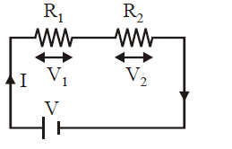
The equivalent resistance in series is given by
(Req)s = R1 + R2 + ...+ Rn
Equivalent resistance of same resistances connected in series is always greater than the greatest of individual resistance.

Potential division rule in series combination

RESISTANCES IN PARALLEL
Two or more resistors are said to be connected in parallel if the same potential difference exists across all resistors.
The equivalent resistance is given by

The equivalent resistance in a parallel combination is always less than the value of the least individual resistance in the circuits.
Current division rule in parallel combination
;

In a given combination of resistors, when you want to detect whether the resistances are in series or in parallel then see that if the same current flows through two resistors then these are in series and if same potential difference is there across two resistors then these are in parallel potential diff across each resistor is the same & is equal to the applied potential difference.
HOW TO FIND EQUIVALENT RESISTANCE?
SUCCESSIVE REDUCTION
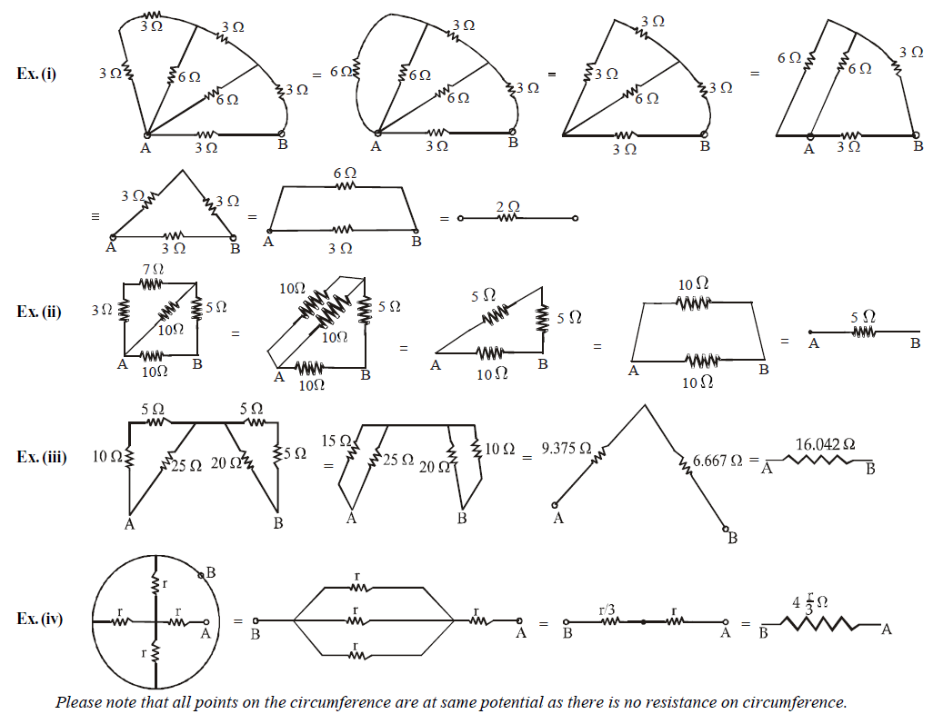
This method is applicable only when the resistors can be clearly identified as in series or parallel. Let us take some examples to find resistance between ends A and B.
Ex.(v) Infinite series :

We observe that there is a repetitive unit extending to infinity on the left hand side. We assume that the equivalent resistance of all the units except one (shown dotted) is equal to X ohm. The equivalent circuit will be as shown below.
The equivalent resistance across A and B is

Please note that RAB can be taken as X because if you add one unit to the sum of infinite units, then it will be approximately the same.

Solve the equation as a normal algebraic equation to find X.
AXIS SYMMETRY
Ex.(i) The circuit shown in the figure is symmetrical about XAEBY axis. This is because the upper part of the axis is the mirror image of lower part (resistors and current direction both)

∴ IAC = IAD; ICB = IDB ;
IAE = IEB ( wheatstone bridge principle)
⇒ ICE = IED = 0
Therefore the circuit can be redrawn. It is now easier to find resistance between X and Y.
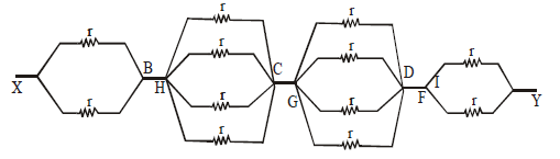
Ex.(ii) The circuit shown is symmetrical about axis XY. Therefore
VB = VH ; VC = VI = VG; VD = VF
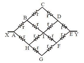
Therefore the circuit can be redrawn as
Ex.(iii) The circuit is asymmetric about the dotted line
∴ IBG = IGC; IFG = IGE and IAG = IGB
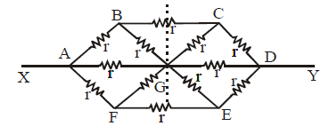
Therefore the equivalent circuit is

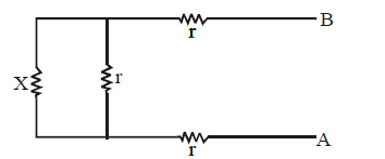
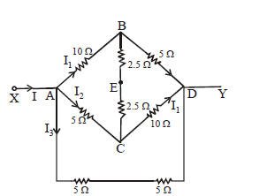
SHIFTED SYMMETRY

The diagram given above is symmetrical but the positions of the resistances are shifted. Let I be the current in the circuit from A. The same leaves the circuit at C. Let current in AB, AD and AE be I1 , I2 and I3 respectively. Since the same current flows in AE and EC, the detached equivalent circuit can be drawn as
POINTS TO REMEMBER
Equivalent resistance between A and B of the resistors connected as shown in the figure below:

Wheatstone bridge
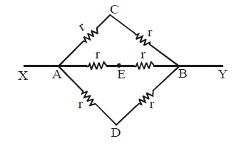
PATH SYMMETRY
All paths from one point to another which have the same setting of resistances have the same amount of currents.
Example :

Twelve wires each having resistance r are joined to form a cube. We have to find the equivalent resistance across A and B.
By path symmetry, IAB = IBC = IAD = IDC = I
∴ IAE = I– 2I1 ⇒ IGC = I– 2I1,
Since current in AB = current in BC
⇒ IBF = 0
Also IAD = IDC ⇒ IDH = 0
The equivalent circuit will be as shown. The resistance is now clearly visible as in series and in parallel.

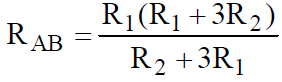
STAR-DELTA CONNECTION

; ; ;

;
;
;
Using delta to star conversion
If none of the above method works then we may use Kirchhoff’s method which will be discussed later
COMMON DEFAULTS
Resistors are not just in series or in parallel if they look so geometrically, e.g. the resistors in the diagram are not in parallel but in series.

These resistors across A and B are in series, as the same current passes through them.
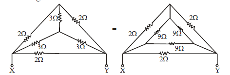
This is a common thinking that current which comes out from the positive terminal of a battery is used up till it reaches the negative terminal. But in fact the current remains the same in a branch. In fact a potential drop takes place across a resistor.
IA = IB = IC = ID = 1 amp
VA = VB = +5V
VC = VD = 0V
This means that a potential drop of 5V takes place across the resistor
🗴 Incorrect : If two resistances are not in series then it is in parallel and vice-versa.
✓ Correct : The above thinking is incorrect. We may have resistances which are neither in series nor in parallel.
COLOUR CODING FOR CARBON RESISTOR AND THEIR STANDARD VALUES
It is a system of colour coding used to indicate the values of resistors.
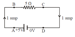
For the fixed, moulded composition resistor, four colour bands are printed on one end of the outer casing as shown below.
The colour bands are always read left to right from the end that has the bands closest to it.
The first and second colour bands, represent the first and second significant digits respectively, of the resistance value.
The third colour band is for the number of zeros that follow the second digit.
In case the third band is gold or silver, it represents a multiplying factor of 0.1 or 0.01.
The fourth band represents the manufacturer's tolerance. It is a measure of the precision with which the resistor was made.
If the fourth band is not present, the tolerance is assumed to be ± 20%.
Resistor colour coding: The resistance is indicated by using electronic colour codes. It contains 4 bands. The first band indicates the first significant figure of resistance, the second band indicates the second significant figure, the third band indicates a decimal multiplier, and the fourth band indicates tolerance that the resistor can withstand. In the absence of the 4th band, a default tolerance of 20% is taken.

Resistor colour coding
Standard value of colour codes for carbon resistors


To learn the above table of colour codes of resistors let us learn this interesting sentence :
BB ROY of Great Britain has a Very Good Wife.
In the above sentence the capital letters have the following meaning :
B-Black, B-Brown, R-Red, O-Orange, Y-Yellow, G-Green, B-Blue, V-Violet, G-Gold, W-White
Remember the colour in the above order and the corresponding digits from 0 to 9 and also the multiplier with the power to 10 from 0 to 9.
Commercial resistors are of two types
Wire round resistor made by winding of wires of alloy manganins, constantan and nichrome.
Carbon resistors have low cost and are compact.
THERMISTOR
A thermistor is a heat sensitive resistor usually made up of semiconductor. The oxides of various metals such as Nickel, iron, copper etc. temperature coefficient of thermistor is –ve but is usually large, of the order of 0.04/ºC.
The V–I curve of the thermistor is as shown.
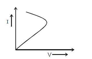
Thermistors are used for resistance thermometers in very low temperature measurement of the order of 10K and to safeguard electronic circuits against current jumps because initially thermistors have high resistance when cold and its resistance drops appreciably when it heats up.
JOULE’S LAW OF HEATING
It states that the amount of heat produced in a conductor is directly proportional to the
square of the current flowing through the conductor,
(q, T – constant)
i.e. H ∝ i2
resistance of the conductor
(i, T – constant)
i.e. H ∝ R
time for which the current is passed
(i, R, – constant)
i.e., H ∝ t
Thus, H = i2 RT joule = i2 RT/4.2 cal
ELECTRIC POWER
It is defined as the rate at which work is done in maintaining the current in an electric circuit.
Electric power, P = VI = I2R = V2/R watt or joule/second.
Electric energy : The electric energy consumed in a circuit is defined as the total work done in maintaining the current in an electric circuit for a given time.
Electric energy = VIt = Pt = I2 Rt = V2 t / R
The S.I. unit of electric energy is joule (denoted by J)
where 1 joule = 1 watt × 1 second = 1 volt × 1 ampere × 1 sec.
In household circuits the electrical appliances are connected in parallel and the electrical energy consumed is measured in kWh (kilowatt hour).
1 kWh (1 B.O.T. unit) = 1000 Wh = 3.6 × 10⁶ J
ELECTROMOTIVE FORCE AND INTERNAL RESISTANCE OF A CELL
An emf (electromotive force) device has a positive terminal (at high potential) and a negative terminal (at low potential). This device is responsible for moving positive charge within itself from negative terminal to positive terminal.

For this to happen, work is done by some agency in the emf device. The energy required to do this work is chemical energy (as in a battery), mechanical energy (as in an electric generator), temperature difference (as in a thermopile).
The emf is thus given by the formula
The S.I unit of emf is (V)
POINTS TO REMEMBER
Electromotive force is not a force but a potential difference.
E.m.f. can be defined as the work done in moving a charge once around a closed circuit.
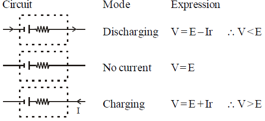
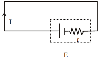
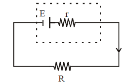
INTERNAL RESISTANCE (r)
The potential difference across a real source of emf is not equal to its emf. The reason is that the charge which is moving inside the emf device also suffers resistance. This resistance is called internal resistance of the emf device.

E = IR + Ir = V + Ir
⇒ V = E – Ir
POINTS TO REMEMBER
For a cell
Emf is the property of a cell but terminal potential difference depends on the current drawn from the cell.
SHORT CIRCUITING
When the terminals of an emf device are connected with a conducting path without any external resistance then
E = Ir ⇒

Since internal resistance has a very small value, therefore a very high current flows in the circuit producing a large amount of heat. This condition is called short circuiting.
During short circuiting, the terminal potential difference is zero.
COMBINATION OF CELLS
SERIES COMBINATION OF CELLS

Equivalent Emf
EAB = E1 + E2 + ... + En
Equivalent internal resistance,
RAB = r1 + r2 + ....... + rn
PARALLEL COMBINATION OF CELLS

Equivalent emf

Equivalent internal resistance
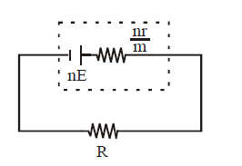
MIXED GROUPING OF CELLS
If the cells are connected as shown below then they are said to be in mixed grouping.

Equivalent emf EAB = nE
Equivalent resistance =
Where n = no. of cells in a row. and
M = no. of rows
If this equivalent cell is attached to an external resistance R then

POINTS TO REMEMBER
The condition for maximum current through external resistance R
⇒ R = nr/m
In other words, when external resistance is equal to total internal resistances of all the cells.
The maximum current

Maximum power dissipation for the circuit shown in fig.
Power

For maximum power across the resistor
,

On solving, we get R = r
This is the condition for maximum power dissipation.
If identical cells are connected in a loop in order, then emf between any two points in the loop is zero.
If n identical cells are connected in series and m are wrongly connected then
Enet = nE – 2mE
FARADAY’S LAW OF ELECTROLYSIS
1st law : The mass of the substance liberated or deposited at an electrode during electrolysis is directly proportional to the quantity of charge passed through the electrolyte.
i.e., mass m ∝ q = Zq = Z It,
where Z = electrochemical equivalent (E.C.E.) of substance.
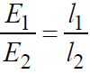
2nd law : When the same amount of charge is passed through different electrolytes, the masses of the substance liberated or deposited at the various electrodes are proportional to their chemical equivalents, i.e.

where m1 and m2 are the masses of the substances liberated or deposited on electrodes during electrolysis and E1 and E2 are their chemical equivalents.
FARADAY'S CONSTANT
Faraday constant is equal to the amount of charge required to liberate the mass of a substance at an electrode during electrolysis, equal to its chemical equivalent in gram (i.e. one gram equivalent)
One faraday (1F) = 96500 C/gram equivalent.
POINTS TO REMEMBER
If ρ is the density of the material deposited and A is the area of deposition, then the thickness (d) of the layer deposited in electroplating process is .
The back e.m.f. for water voltameter is 1.67 V and it is 1.34 V for CuCl2 electrolytes voltameter with platinum electrodes.
96500 C are required to liberate 1.008 g of hydrogen.
2.016 g of hydrogen occupies 22.4 litres at N.T.P.
E.C.E. of a substance = E.C.E. of hydrogen × chemical equivalent of the substance.
SEEBECK/THERMOELECTRIC EFFECT
When an electric circuit is composed of two dissimilar metals and the junctions are maintained at different temperatures, then an emf is set up in the circuit. This effect is known as thermoelectric or seebeck effect.
THERMOCOUPLE
It is a device in which heat energy is converted into electrical energy. Its working is based on seebeck effect. It has two junctions of two dissimilar metals.

Some of the elements forming thermo-electric series
Sb, Fe, Zn, Cu, Au, Ag, Pb, Al, Hg, Pt, Ni, Bi
Lead (Pb) is thermo-electrically neutral
At the cold junction, current flows from the element occuring earlier into the element occurring later in the series.
For example: In Cu–Fe thermocouple, current flows from Cu to Fe at hot junctions.
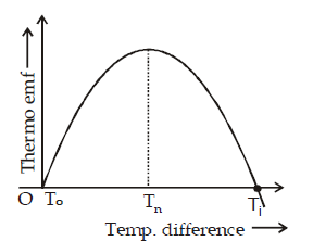
NEUTRAL TEMPERATURE (Tn)
It is that temperature of hot junction for which the thermo emf produced in a thermocouple is maximum. It depends upon the nature of the material of thermocouple but is independent of temperature of cold junction.
TEMPERATURE OF INVERSION (Ti)
It is that temperature of the hot junction for which the thermo emf becomes zero and beyond this temperature, the thermo emf in a thermocouple reverses its direction.
It depends upon the nature of the material of thermocouple and temperature of cold junction
Let To, Tn, Ti be the temperature of cold junction, neutral temperature and temperature of inversion then
With temperature difference T between hot and cold junctions, the thermo-e.m.f. is given by
E = αT + βT2
where α and β are Seebeck coefficients
At Tn, (dE/dT) = 0
∴ Tn = – α/2β and Ti = – α/β, when To = 0
S = dE/dT is called thermo-electric power.
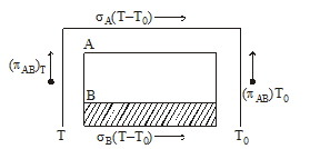
PELTIER EFFECT
It states that if current is passed through a junction of two different metals the heat is either evolved or absorbed at that junction. It is the reverse of the seebeck effect.
The quantity of heat evolved or absorbed at a junction due to the Peltier effect is proportional to the quantity of charge crossing that junction.
PELTIER COEFFICIENT (π)
It is defined as the amount of heat energy evolved or absorbed per second at a junction of two different metals when a unit current is passed through it.
The Peltier heat evolved or absorbed at a junction of a thermocouple = πI t
where I = current passing through the junction for time t.
where T and (T + dT) are the temperature of cold and hot junctions of a thermocouple and dE is the thermo emf produced.
(Seebeck coefficient)
THOMSON EFFECT
If a metallic wire has a non uniform temperature and an electric current is passed through it, heat may be absorbed or produced in different sections of the wire. This heat is over and above the joule heat I2Rt and is called Thomson heat. The effect is called Thomson effect.
If a charge ΔQ is passed through a small section of given wire having temperature difference ΔT between the ends, Thomson heat, ΔH = σ ΔQ ΔT
where σ is constant for a given metal at a given temperature.
Thomson emf, σ ΔT, is defined as σ ΔT = ΔH/ΔQ.
Note:- σ is positive if heat is absorbed when a current is passed from low temp. to high temperature. σ is numerically equal to P.D. developed between two points of the conductor differing in temp. by 1ºC.
POINTS TO REMEMBER
The actual emf developed in a thermocouple loop is the algebraic sum of the net Peltier emf and the net Thomson emf developed in the loop.
If S, π and σ are the Seebeck coefficient, Peltier coefficient, and Thomson coefficient respectively then it is found that
For Peltier effect or Thomson effect, the heat evolved or absorbed is directly proportional to current. But for Joule's law of heating, the heat produced is directly proportional to the square of the current flowing through it.
Thermo-emf set up in a thermocouple when its junctions are maintained at temperature T1 and T3 (i.e. ) is equal to the sum of the emfs set up in a thermocouple when its junctions are maintained first at temperature T1 and T2 (i.e. ) and then at T2 & T3 (i.e. ) i.e.
It is called law of intermediate temperature.
KIRCHOFF’S LAWS AND ELECTRICAL CIRCUIT
Many practical combinations of resistors cannot be reduced to simple series, parallel combinations. For example the resistors in the figure are neither in series nor in parallel.
The use of Ohm’s law is not sufficient to solve such problems. Kirchoff’s laws are used in such cases.
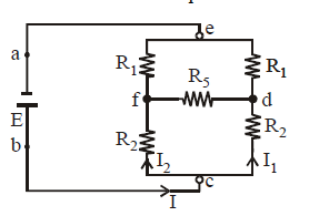
We will often use the term junction and loop, so let us first understand the meaning of these words. A junction in a circuit is a point where three or more conductors meet. A loop is a closed conducting path. In the above figure e, f, d, c are junctions. a, b, are not junctions. The various loops are efde, cdfc, eabcf and eabcde.
KIRCHOFF’S JUNCTION LAW
(Based on conservation of charge)
At any junction, the sum of currents entering the junction must be equal to the sum of currents leaving it. If this is not so, charges will accumulate at the junction. This cannot happen as this would mean high/low potential maintained at a point in a wire without external influence.
When we apply this rule at junction c, we get I = I1 + I2
KIRCHOFF’S LOOP LAW
(Based on energy conservation)
The algebraic sum of changes in potential around any closed loop of a circuit must be zero.
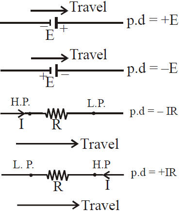
Sign convention for using loop law
If we move a loop element (resistor, emf device, capacitor, inductor etc.) in the direction of increasing potential, we take the potential difference positive and vice-versa.
PROBLEM SOLVING TRICKS FOR USING KIRCHOFF’S LAW
Draw a circuit diagram large enough to show all resistors, emf device, capacitors, currents clearly.
Take into account the resistance of voltmeter/ammeter/internal resistance of a cell (if given).
Assume the direction of current in all branches. It may be noted here that one branch has only one direction of current. It is best to use junction law simultaneously while drawing currents. This helps to reduce the number of unknown quantities.
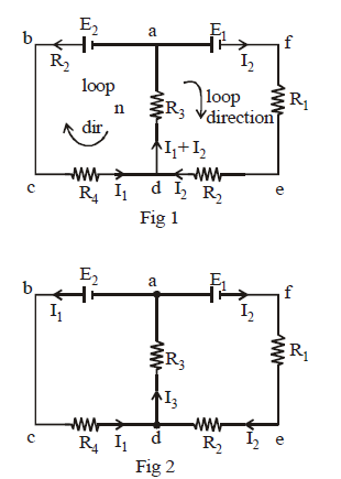
In the above circuits we arbitrarily assumed the direction of current I1 in branch abcd as anti-clockwise and the direction of current I2 in branch afed as clockwise.
In figure 1 we have two unknown currents (I1, I2) whereas in figure 2 we have three unknown currents (I1, I2 and I3). The first figure is a better option for solving problems. In figure 1 we used the junction rule at d simultaneously while labelling currents.
In a branch containing a capacitor, the current is zero when d.c is applied and steady state conditions are achieved.
Now we need as many independent equations as there are conditions unknown. If we have to find a particular unknown, we should ensure that the unknown appears in one of the equations made by us.
For making equations choose the loop and travel the loop completely. We may travel the loop in clockwise or anti-clockwise directions. While using the second law use sign conventions properly.
Solve the equations formed to find the unknown quantities. If any value of current comes out to be negative then that particular current is in the opposite direction to that assumed.
APPLICATIONS
Let us use the second law in the loop abcda of figure 1 taking the loop in anti-clockwise direction starting from a.
+ E2 – I1R4 – (I1 + I2) R3 = 0
For loop afeda, moving the loop in clockwise direction we get –
E1 – I2 R1 – I2R2 – (I1 + I2)R3 = 0
NODE METHOD TO APPLY KIRCHOFF’S LAW (OPEN LOOP METHOD)
Step 1 : We select a reference node and assume its potential to be (zero/x)V
Step 2 : We calculate the voltage of other selected points w.r.t. the reference node
Step 3: We find some independent node (whose voltage is not known). We apply Kirchoff’s law to find the relevant values.
WHEATSTONE BRIDGE
The condition for balanced wheatstone bridge
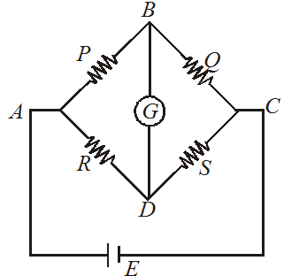
also
Note that when the battery and galvanometer of a Wheatstone bridge is interchanged, the balance position remains undisturbed, while sensitivity of the bridge changes.
In the balanced condition, the resistance in the branch BD may be neglected
Example : Resistance connected to BC may be neglected.

Note:- In a Wheatstone bridge, the deflection in a galvanometer does not change, if the battery and the galvanometer are interchanged
Measuring temperature with the help of Wheatstone bridge
At balancing

When P = Q then ΔR = S α ΔT
COMMON DEFAULT
🗴 Incorrect. If the current flows in a wire, there has to be a potential difference. The potential drop takes place only when current passes through a resistor.

✓ Correct. In the diagram, the three resistors are in parallel. The potential at A is equal to the potential at C. Current flows in wire 1 but there is no potential drop across A and C.
🗴 Incorrect. If the potential difference between the points is zero, there is zero current between the two points.
✓ Correct. There is no p.d. between A and C still current flows in segment 1.
METER BRIDGE OR SLIDE WIRE BRIDGE
PRINCIPLE
The Principle of Meter Bridge is based on the principle of balanced Wheatstone bridge.
USE
The Meter bridge is used to find an unknown resistance.
WORKING
Let P be the unknown resistance.
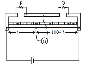
At the balance point, when deflections on the Galvanometer reads a zero,
If P is known then Q can be calculated.
POTENTIOMETER
PRINCIPLE
The p.d. across a resistance wire is directly proportional to its length provided I, r and A are constant.
V = IR = I ρ
⇒ V α l [ I, ρ and A are constant]
WORKING
PQ is the resistance wire of a potentiometer which is generally made up of constantan or nichrome. One end P is connected to the positive terminal of the battery B while the negative terminal is connected to Q through a Rheostat (Rh) and key (K). This is the main circuit.
A cell whose emf has to be measured is also connected to the potential wire in such a way that the positive terminal is connected with P and negative terminal is connected to a galvanometer and then to a jockey (J) which is free to slide along the wire

There is a potential drop along PQ.
The potential drop per unit length along PQ is called potential gradient.
When the jockey is pressed on some point, current flows from E to P (⇒). Also current that comes from B after reaching P divides into two parts. One part moves towards A and the other towards E (→). Three cases may arise.
IB > IE. This happens when VPC > E. One side deflection in galvanometer
IB = IE. This happens when VPC = E, Zero deflection in galvanometer
IB < IE . This happens when VPA < E. Other side deflection in the galvanometer.
Note:-
At null point since no current flows through E therefore it is said to be in the condition of open circuit.
More is the length of potentiometer, higher is the sensitivity of potentiometer and smaller is the potential gradient.
Potentiometer will work only when B > E. Also the positive terminal of the batteries is connected at P. If any of the above conditions is not followed, we do not get a null point.
USES
Comparison of emfs of cells
To find internal resistance of a cell
Emf can be measured by potentiometer and not voltmeter.

MEASURING INSTRUMENTS
GALVANOMETER
It is an instrument used to detect small currents in a circuit.
The current required for full scale deflection in the galvanometer is called full scale deflection current and is denoted by Ig.
CURRENT SENSITIVITY OF A GALVANOMETER
It is defined as the deflection produced in the galvanometer, when unit current flows through it.
Current sensitivity
, and its unit is rad A–1

Current sensitivity can be increased either by decreasing C i.e. restoring torque per unit twist or increasing B.
VOLTAGE SENSITIVITY OF A GALVANOMETER
It is defined as the deflection produced in the galvanometer when a unit voltage is applied across the two terminals of the galvanometer.
Voltage sensitivity
,

its unit is rad V–1
AMMETER
Ammeter is used to measure current in a circuit. Ammeter is always connected in series in the circuit as shown.

Conversion of a galvanometer into an ammeter

For this, we connect a small resistance S (called shunt) in parallel with the galvanometer.
Mathematically, Ig × G = (I – Ig) S
where I is the maximum current which ammeter can measure. G is the resistance of the galvanometer and Ig is the current of full scale deflection in the galvanometer. S is shunt.
RESISTANCE OF THE AMMETER
Since shunt is a small resistance. Therefore the resistance of the ammeter is very small.
The above arrangement is made so that when we connect an ammeter in series to measure current, it does not change the original current to a large extent. The change is in fact very small. Also since a galvanometer is a sensitive device and cannot take large currents, this arrangement serves the purpose. Most of the current entering the ammeter passes through the shunt as current always prefers a low resistance path.
An ideal ammeter is one which has zero resistance.
The range of ammeter can be increased but cannot be decreased below Ig.
VOLTMETER
Voltmeter is used to measure potential difference across a resistor. Voltmeter is always connected in parallel across a resistor.
Conversion of a galvanometer into a voltmeter

For this, we connect a large resistance R in series with the galvanometer.
The potential difference which has to be measured is across the external resistance i.e. across points a and b.
Let it be V. Then V = Ig (G + R)
where V is the maximum potential difference that the voltmeter can measure and R is the large resistance connected in series with the galvanometer
The resistance of the voltmeter will be RV = G + R
Since R is a large resistance. Therefore the resistance of the voltmeter is very large.
An ideal voltmeter is one which has infinite resistance.
The range of voltmeter can be increased and decreased.
Note:- When ammeter/voltmeter is connected in the circuit, the current or voltage indicated by these is less than the actual values in their absence.
Important Notes on Resistors
They reduce current flow and lower voltage levels within the circuit.
It is a passive element ie it only consumes power but doesn’t generate.
A circuit is composed of conductors like wire, power source, load, resistor, and switch.
It starts and ends at the same point. In general, a copper wire without insulation is used as a conductor.
In an electric circuit, different components are connected either in series or in parallel to produce different resistive networks.
In the same circuit, resistors can be connected in both parallel and series across different loops to produce a more complex resistive network known as mixed resistor circuits.
Resistors in Series
A circuit is connected in series when the same amount of current flows through the resistors.
The voltage across each resistor is different.
If any resistor is broken, then the entire circuit is turned off.
The construction of a series circuit is simpler than a parallel circuit.
The sum of potential differences across individual resistors is equal to the potential difference applied by the source.
Equivalent resistance R = R1 + R2 + R3.
Resistors in Parallel
A circuit is connected in parallel when the voltage is the same across the resistors.
It can be connected or disconnected easily without affecting other elements in the circuit.
The sum of electric currents flowing through individual resistors is equal to the electric current drawn from the source.
Equivalent resistance 1/R = 1/R1 + R2 + R3.
Problems For Practice
Q 1. When electrons gather in a metal from lower to higher potential, does this indicate that all the free electrons of the metal are moving in the same direction? (Delhi 2012)
Ans.

No, all the free electrons of the metal will not move in the same direction. Only the drift velocities of the electrons are superposed over their haphazard thermal velocities. The solid line refers to the random path followed by a free electron in the absence of an external field. The electrons that are moving from A to B are making 6 collisions on its path. When an electric field is applied, the dotted curve shows how the random motion of the same electron gets modified.
Q 2. A 10 V battery of negligible internal internal resistance is connected across 200 V and a resistance of 38? as shown in the figure below. Derive the value of the current in circuit. (Delhi 2013)

Ans. By applying Kirchhof’s rule we get,
200 - 10 = 190 V
And I = V/R = 190 / 38 = 5 A
Q 3. What do you mean by the term ‘Mobility’ of charge carried in a conductor? Write its S.I. unit. (Delhi 2014)
Ans. Mobility of charge carried in a conductor is defined as the magnitude of the drift velocity per unit electric field E.

Q 4. Obtain the expression for the current in a conductor of a cross sectional area A in terms of drift velocity. (Comptt. All India 2013)
Ans. Drift velocity can be defined as the velocity of the free electrons with which they drift towards the positive terminal under the influence of an external electric field. The drift velocity of electron is of the order of 10-5 m/sec. Expression for current in terms of drift velocity is, I = Anevd
Assume a conductor of length l and of uniform cross section area A.
Therefore, volume of the conductor AI
Total number of free electrons in the conductor is Aln if n is the number of conductors.
If e is the charge on each electron, then the total charge on all A of the free electrons in the conductor, q = Alne
The electric field set up across the conductor of potential difference V is,
E = V / I
I = neAvd
For this field, the free electrons in the conductor will begin to move with a drift velocity Vd towards the positive terminal of the battery.
Thus, time taken by the free electrons to cross the conductor,

Since A, n and e are constants
Hence, I ∞ Vd
Hence, the current flowing through a conductor is directly proportional to the drift velocity.
Q 5. State Kirchhoff’s rule and explain briefly how these rules are justified. (Delhi 2014)
Ans. There are two Kirchhoff’s laws to solve complicated electrical circuits. Using these laws and equations for individual components such as a resistor, capacitor, and inductor, we can analyse circuits.
Junction Rule: The algebraic sum of all currents meeting at a junction in a closed circuit is zero. It follows the law of conservation of charge. In this rule, the total current entering the junction is the same as the charge leaving the junction as there is no charge lost. This current law can be applied to analyse parallel circuits.
Loop Rule: The algebraic sum of all potential differences or voltage in any closed circuit is zero. It follows the law of conservation of energy. When you start at any point of the loop and continue in the same direction, voltage drops in all directions either in negative or positive and returns to the same point.
These two laws are justified on the basis of the law of conservation of charge and the law of conservation of energy respectively.
Q 6. Obtain the conditions for balance conditions in a Wheatstone bridge by using Kirchhoff’s rules. (Delhi 2015)
Q 7. (a) Obtain the equation between current density J and potential difference V across a current carrying conductor of length area of cross section A and number density of free electrons.
(b) Estimate the average drift speed of conduction electrons in a copper wire of cross sectional area 1.0 x 10⁻⁷ m2 carrying a current of 1.5 A [Consider that the number density of conduction electrons is 9 x 1928 m-3]. (Comptt. Delhi 2012)
Ans. (a) Considering a potential difference V is applied across a conductor of length l and of uniform cross section A
The electric field E set up inside the conductor is,
E = V/l
Under the influence of the field , the free electrons drift in the opposite direction with an average drift velocity Vd.
Now, let the number of electrons per unit volume = n
Charge on an electron = e
Number of electrons in length l of the conductor is n x volume of the conductor = n x Al
Total charge in length l of the conductor is
q = enAl … (i)
All electrons which entre the conductor at the right end will pass through the conductor at the left end in time,
Thus, the current density of a metallic conductor is directly proportional to the drift speed of electrons.
(b)

Q 8. State the principle of potentiometer.
(i) Write the principle of working potentiometer.
(ii) In the given potentiometer circuit AB is a uniform wire of length of 1 m and resistance 10?. Calculate the gradient along the wire along with the balance length AO (=I). (Delhi 2017)

Ans. (i)
(a) The basic principle of a potentiometer is that when a constant current flows through a wire of uniform cross sectional area and composition, the potential drop across any length of the wire is in direct proportion to that length.
v ∞ I
The comparison of emf of two cells- All the ends of potentiometer are connected to a battery Bx, key K and rheostat Rh in a way that the positive terminal of battery B is attached to the end A of the wire which completes the primary circuit.
Now, the positive terminals of the cells C1 and C2 are connected to A and the negative terminals to the jockey J through a two way key and a galvanometer and this is the secondary circuit.
Method-
(i) By closing key K, a potential difference is formed and rheostat is so adjusted that when jockey J’ is made to touch the ends A and B of wire, the deflection in the galvanometer is on both sides. Considering that in this position, the potential gradient is k.
(ii) Now plug is inserted between the terminals 1 and 3 so that the cell C1 is involved in the secondary circuit and jockey J slides on the wire at P1 to obtain the null point. The distance of P1 from A is measured as, AP1= l1
ε 1 = kl 1... (i)
(iii) Now plug is taken off between the terminals 1 and 3 and inserted between the terminals 2 and 3 in order to bring cell C2 in the circuit. Jockey is slided on wire and the null deflection position P2 is noted. Assuming the distance of P2 from A is l2, that is AP2 = Z2.
The emf of cell C2, e2 = kl2 …(ii)
... (iii)

Therefore, the emfs of the cells can be compared where if one is a standard cell, then the emf of the other cell will be calculated.
(b) The causes of one sided deflection-
(i) Potential difference between the ends of potentiometer wire is less than the emf of the cell in the secondary circuit.
(ii) The positive side of the driving cell is connected to the negative terminal of the cell in the secondary circuit.
Q 9. If the temperature of a good conductor decreases, how does the relaxation time of electrons in the conductor change? (2 Marks)
Ans. We know:
ρ=m/ne2𝛕
When the temperature decreases, collision decreases, and thus relaxation time increases which in turn decreases the resistivity.
Q 10. Name any one material having a small value of temperature coefficient of resistance. Write one use of this material. (1 Mark)
Ans. Nichrome, an alloy has a small value of temperature coefficient of resistance. It is used for making standard resistance coils.
Q 11. Two wires A and B are of the same metal and of the same length and have their areas of the cross-section in the ratio of 2:1 if the same potential difference is applied across each wire in turn, what will be the ratio of current flowing in A & B? (2 Marks)
Ans. Since R𝛂 1/A
If the area is in the ratio 2:1 resistance will be in the ratio 1:2.
And I = V/R ⟹ I=1/R
Thus, the current will be in the ratio of 2:1
Q 12. The plot of the variation of potential difference across a combination of three identical cells in series, versus current is shown in the figure. What is the emf of each cell? (Delhi 2008) (2 Marks)
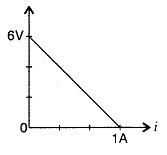
Ans. Total emf of three cells in series = P.D corresponding to zero current = 6V
Thus, emf of each cell =
6V/3 = 2V
Q 13. Two wires of equal length, one of copper and the other of manganin have the same resistance. Which wire is thicker? (All India 2012) (3 Marks)
Ans.
For both wires R and l are the same and ρ copper < p manganin.
∴ A copper < A manganin
i.e. Manganin wire is thicker than copper wire.
Q 14. A cell of emf ‘E’ and internal resistance ‘r’ draws a current ‘I’. Write the relation between terminal voltage ‘V’ in terms of E, I and r. (Delhi 2013) (1 Mark)
Ans. V = E – I
Ques 15. Why is the terminal voltage of a cell less than its emf? (Comptt. All India 2013) (1 Mark)
Ans. The terminal voltage of a cell is less than emf because some current, however small, may be drawn to measure terminal voltage due to the internal resistance of the cell.
Current Electricity
1. The directed rate of flow of electric charge through any cross-section of a conductor is known as electric current.
If ∆Q charge flows in time ∆t, then current at any time t is given by

NOTE:
- Electric Current is a scalar quantity.
- I is in the direction of flow of positive charge and opposite to the direction of flow of negative charge(electrons).
- SI unit of current is ampere and is represented by A.

2. The current density at a point in a conductor is the ratio of the current at that point in the conductor to the area of cross-section of the conductor at that point provided the area is held normal to the direction of flow of current.

NOTE:
Current density is a vector quantity.
3. Flow of Electric Charge in Metallic Conductors
- Among the solids, all metals are good conductors of electricity. The cause of conductance is free electrons.
- In Case of a Solid Conductor (i.e. Cu, Fe, Ag, etc) atoms are tightly bound to each other. There are large number of free electrons in them.
- In Case of a Liquid Conductor Like electrolytic solution, there are positive and negative charged ions which can move on applying electric field.
4. Drift Velocity
It is defined as the average velocity with which the free electrons move towards the positive end of a conductor under the influence of an external electric field applied.

The order of drift velocity of electron is 10⁻⁴ ms⁻¹.
5. Electric current in terms of drift velocity

6. Current density at any point of conductor, (j = ne vd)

where, j is a vector quantity.
7. Mobility The ratio of drift velocity of electrons and the applied electric field is known as mobility.

8. Ohm’s Law :
At constant temperature, the potential difference V across the ends of a given metallic wire (conductor) in an circuit (electric) is directly proportional to the current flowing through it.
![]()


The variation of current w.r.t. applied potential difference is shown with the help of following graph.
V = IR
where, R = resistance of conductor
No effect of V and I on R because as V increase, I increase but R remains the same.
9. Resistance of
a Conductor Mathematically, it is the ratio of potential difference
applied across the ends of conductor to the current flowing through it.
=> R = V/I
SI unit is ohm (Ω).
Resistance can also be written as,
R =ρ L/A
where,
L = length of the conductor, A = area of cross-section and ρ =
constant, known as resistivity of the material. It depends upon nature
of the material.
10. Relationship between resistivity and relaxation time

Specific resistance or resistivity (𝝆) depends on material of conductor, not on the length or cross-sectional area (A) or geometry of the conductor.
11. Since Resistance of a conductor is given by


12. Temperature Coefficient of resistance at 0⁰C, 𝞪 is defined as the change in resistance per Ohm for change in temperature from 0⁰ C to t⁰ C .
The value of 𝞪 is given by the following relation.


13. Conductivity It is defined as the reciprocal of resistivity of a conductor.
It is expressed as,

SI unit is mho per metre (Ω⁻¹.m⁻¹) or Siemen per metre ( S.m⁻¹ )
14. Superconductivity The resistivity of certain metal or alloy drops to zero when they are cooled below a certain temperature is called superconductivity.
It was observed by Prof. Kamerlingh in 1911.
15. Relationship between current density (j), electric field (E)and conductivity (σ ) is
j = σ E
16. Some Important Units

17.Resistance after Elongation
If a conductor is stretched or compresses to n times its original length, then
l′ = n l ⇒ R′ = n2R
where, l′ = new current, R′ = new resistance and R = original resistance.
18. Colour Code of Resistance
- The colour code on carbon resistor remains in the form of coaxial rings.
- The first band represents the first significant figure,
- Second band represents second significant figure ,
- Third band represents multiplier (i.e. power of ten).
- The fourth band represents tolerance.

The resistor shown above the figure has a resistance of 1K𝜴 ± 5%or (1000 ± 5%)𝜴 as
The colours Brown-Black-Red represent the numbers 1-0-2 and golden colour represents the tolerance value ± 5%.
19. Grouping / Combinations of Resistance There are two types of resistance combinations.

(i) Series Combination
In this combination, different resistances are connected end to end.
Equivalent resistance can be obtained as the formula,

NOTE: The total resistance in the series combination is more than the greatest resistance in the circuit.
Derivation of the formula:
Series Combination
While connecting resistors in series we do so by joining them end-to-end such that the same current passes through all the resistors.

V = V1 + V2
V = IR1 + IR2
V = I(R1 + R2)
V = IRs
Equivalent resistance Rₑ𝓆 for series combination is given by
Rs = R1 + R2
The equivalent resistance of a series combination of resistors is equal to the sum of individual resistances.
(ii)
Parallel Combination
In this combination, first end of all the resistances are connected to one terminal and last end of all the resistances are connected to the other terminal.

Equivalent resistance can be obtained by the formula


NOTE: The total resistance in parallel combination is less than the least resistance of the circuit.
Derivation of the formula:
Parallel Combination
While connecting resistors in parallel we do so by joining their one end at one terminal of the source of e.m.f. and the other ends at the other terminal. In parallel combination, same potential difference exists across all resistors.

The main current divides into two parts.
I1 = V/R1
I2 = V/R2
I = I1 + I2
I = V(1/R1 + 1/R2)
I = V/Rp
Here, Equivalent resistance (Rₑ𝓆)⁻¹ for parallel combination is given by
1/Rp = 1/R1 + 1/R2
Reciprocal of equivalent resistance of parallel combination is equal to the sum of the reciprocals of individual resistances.
Problem 1
Find and compare the Current and the equivalent resistance of the combinations in the figure below.

Solution :
In the first figure, there is a series combination of 4 resistances 2 𝜴 each connected to a potential difference of 5 V.
Here, Equivalent resistance Rₑ𝓆 = ( 2+2+2+2 )𝜴 = 8𝜴
As V = I Rₑ𝓆, So, I can be calculated as V / Rₑ𝓆 = 5V/ 8 𝜴 =0.625 A
But in the second figure, there is a parallel combination of 4 resistances 2 𝜴 each connected to a potential difference of 5 V.
Here, Equivalent resistance (Rₑ𝓆)⁻¹ = ( 2⁻¹+2⁻¹+2⁻¹+2⁻¹ )𝜴 = 4. 2⁻¹𝜴 = 2𝜴
So, Rₑ𝓆= 2⁻¹ 𝜴 = 0.5 𝜴
As V = I Rₑ𝓆, So, I can be calculated as V / Rₑ𝓆 = 5V/ 0.5 𝜴 =10 A
It can be observed that the parallel combination allows more current to flow through a circuit.
20. Large Scale Grouping of Resistances: If n identical resistors each of resistance R are connected in
(i) series combination,
Req = n R
(ii) parallel combination,
Req = R/n
Example:
As in problem 1 above, we find that the equivalent resistances of 4 resistors 2𝜴 each in series becomes 2𝜴 x 4 = 8𝜴 while in parallel it is 2𝜴 / 4 = 0.5 𝜴.
(To be continued)
More numerical problems will be added soon.
The sections dealing with the following will also be appended soon.
The internal resistance of a cell,
potential difference and e.m.f of a cell,
the combination of cells in series and in parallel,
Kirchhoff’s laws and simple applications,
Wheatstone bridge, metre bridge (qualitative ideas only)
Potentiometer – principle and its applications to measure potential difference
Potentiometer – for comparing EMF of two cells,
measurement of internal resistance of a cell (qualitative ideas only).